THE "PIPCAM" PORTABLE IMAGING CAMERA
My 1004x-JG is not ideally suited for the Portable Imaging Project as it has a separate bulky interface and requires two power supplies (for the camera and Peltier cooler). The Steve Chambers SC1/2 modified webcam would be more suitable but is much less sensitive, an important consideration when imaging with the small aperture 80mm f5. A better alternative is the SC3 - another Steve Chambers design in which the original webcam chip is replaced with a significantly more sensitive B+W version.
Click here for more information on Steve Chambers modified webcam designs (very little on this page will make much sense unless you have fully digested details of the Vesta mods there!), and please take note of the conditions Steve requires to be met by anyone using his designs. In this way we can hopefully maintain the open manner in which these (and any future) cameras are developed for the benefit of everyone.
PIPCAM MK1
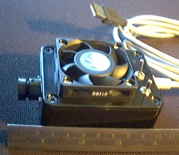
As a first step, a Vesta Pro 675 has been modified to SC1 specification. The camera is air cooled using a microprocessor cooling fan which blows air in through a large hole in the top of the box which exits through holes in the front of the bottom of the box in an attempt to direct the air around the CCD chip. (A ball bearing fan design was used for reduced vibration and, although designed for 12v, it runs happily at reduced speed from the 5v USB supply)
The metal lens housing from a 1/3 inch CCD chip video camera has been fitted, ready for modification to the larger SC3 chip design. This will also be suitable for Peltier cooling if required later, in the same way as my 1004x-JG camera.
The two switches are for the shutter in long/normal exposure modes and for the fan.
To simplify the cabling, a 2-way USB hub and a USB to serial converter were built into the camera. This means the camera can be run with one USB connection to the computer and will work on computers, which do not have serial or parallel ports.
SC1 MODIFIED CAMERA BOARD
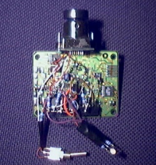
The SC1 exposure control modification is based on a 4066 chip and constructed using the "dead bug" technique. The components required to convert the serial port voltages to 0/5v logic are incorporated into the dead bug circuit (see Steve Chambers design). To make the modification to the Vesta board as risk free as possible, the modification was performed using track cuts where possible rather than pin lifts. Only one pin (10) had to be lifted and a connection was made to a via rather than attempting the difficult connection to pad 10.
Only one of the 4066 tristate switches was used to control the long exposure via software. The connections to pins 8 and 13 were not separated, which means individual control of the two frames (version SC2) is not possible. The shutter control switch is manual direct to pin 10 on the board rather than via the 4066. The amp off mod has not been done in this stage but will probably be applied on conversion to SC3.
A two colour LED has been fitted with the red connected permanently across the USB power supply and the green connected to one of the spare 4066 tristate switches. This means that in normal exposure mode the LED shows yellow when the camera is powered. In long exposure mode, when an exposure is not in progress it shows yellow, changing to red during the exposure.
The LED and microphone were desoldered from the CCD board and the unused strip at the end of the board cut off so it can be squeezed into the project box.
2 WAY USB HUB & USB TO SERIAL COVERTER SUB-ASSEMBLY
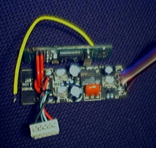
Although chosen for their compactness, the USB hub and serial converter are far too big to fit in the project box. Fortunately, once they are disassembled and the USB and serial connectors removed, (using a combination of desoldering and wire snips) the bare boards are very compact and can be wired together ready to fit in the box.
The ribbon cable connects to the incoming USB cable (salvaged from the Vesta). The multiway connector (cut from the Vesta cable), is soldered to one of the Hub outputs, and connects to the Vesta camera board. The other Hub output goes to the serial converter board (red wires). The yellow lead is from the RTS line on the serial output and feeds the dead bug circuit to control the exposure. The DTR line is not connected at this stage but will be will be used to control the amp off when the conversion to SC3 is made.
The three LEDs on the Hub circuit board were in rather inaccessible positions so they were painted black to eliminate stray light rather than being removed.
PIPCAM MK 1 INTERNALS
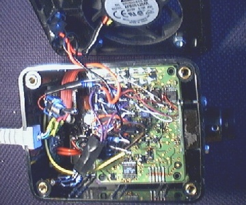
This picture shows everything squeezed into the project box, (just!)
Click here for here first light image of this camera, taken with the 80mm f5 on the Eq1 mount and driven using the Skysensor
1st July 2003