Modifications to the Eq1 "Simple Type" RA Drive
NOTE This section is included for completeness as it has been largely superceded by the decision to adapt the Skysensor 2000 drive system from the main scope for imaging. The original drive is still used for visual work however where the added portability is useful and when it is not convenient to dismantle the main scope drive.
The Eq1 mount came with a "Simple Type" basic DC RA drive. It consists of a battery operated speed controlled DC motor with controls for trimming the speed and to reverse the direction for north and south hemisphere operation.
There are several problems with this drive, particularly if it is to be used for imaging. (Note these have been addressed in a more sophisticated stepper motor version of the RA drive available for the Eq1)
1. The drive controls are fixed to the mount, integral with the motor. This makes it difficult to adjust the drive without disturbing the mount.
2. There are no fast forward and reverse speed settings to enable the motor control to be used to centre the object (The speed control potentiometer has quite a wide range of adjustment and at maximum, the drive runs at approximately 2x speed. However if this is reset to increase the speed, it is difficult to re-trim it to the correct setting)
3. The mount RA slow motion cannot be adjusted manually with the drive engaged. This makes it difficult to centre objects on the CCD chip. (Although the clamping screw can be freed to allow the RA to be adjusted manually, the screw clamps against a flat on the RA shaft, which means the drive can only be engaged at one position on the shaft)
These problems were solved by modifying the mount as follows:-
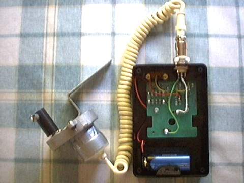
1. The circuit board and battery was separated from the motor and mounted in a separate box with a flexible lead, eliminating the risk of shaking the mount when making drive adjustments
2. A new bracket was fabricated for fixing the motor to the mount. This allowed the motor coupling clamping screw to engage the round area of the RA shaft. This allows the drive to be engaged and disengaged at any position of the shaft. In some examples of the mount this can be achieved just by sliding the coupling along the shaft, but this was not possible for my particular model so a new bracket had to be fabricated (NB This modification increases the risk of slippage, which some users have experienced, but the RA shaft on my mount rotates with a very light touch and with a well balanced mount I have not seen a problem)
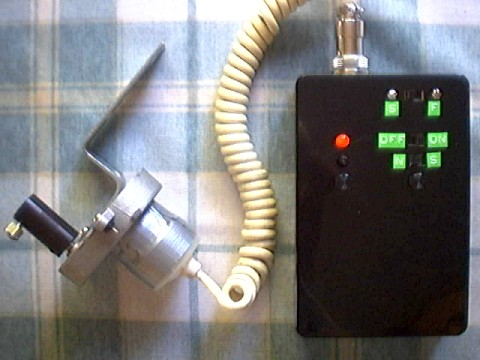
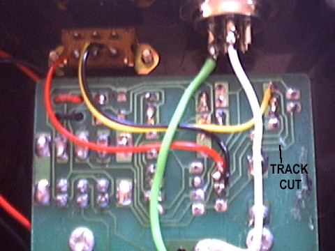
3. An additional switch was wired to the circuit board to allow the motor to be run at maximum speed without disturbing the speed trimming potentiometer. This fast speed, together with the North/South reversing switch can be used to centre objects in RA using the drive. The modification consisted of cutting the track to the wiper of the potentiometer and wiring the switch to connect the feed to the wiper either to the high speed end of the potentiometer track for maximum speed or back to the wiper as standard.
4th July 2003